How to accept inline cable vision inspection without overstating what it proves
Accept an inline vision system against named, observable defects under real production conditions—not a single accuracy score. Electrical integrity, wall thickness and material performance remain separate evidence streams.
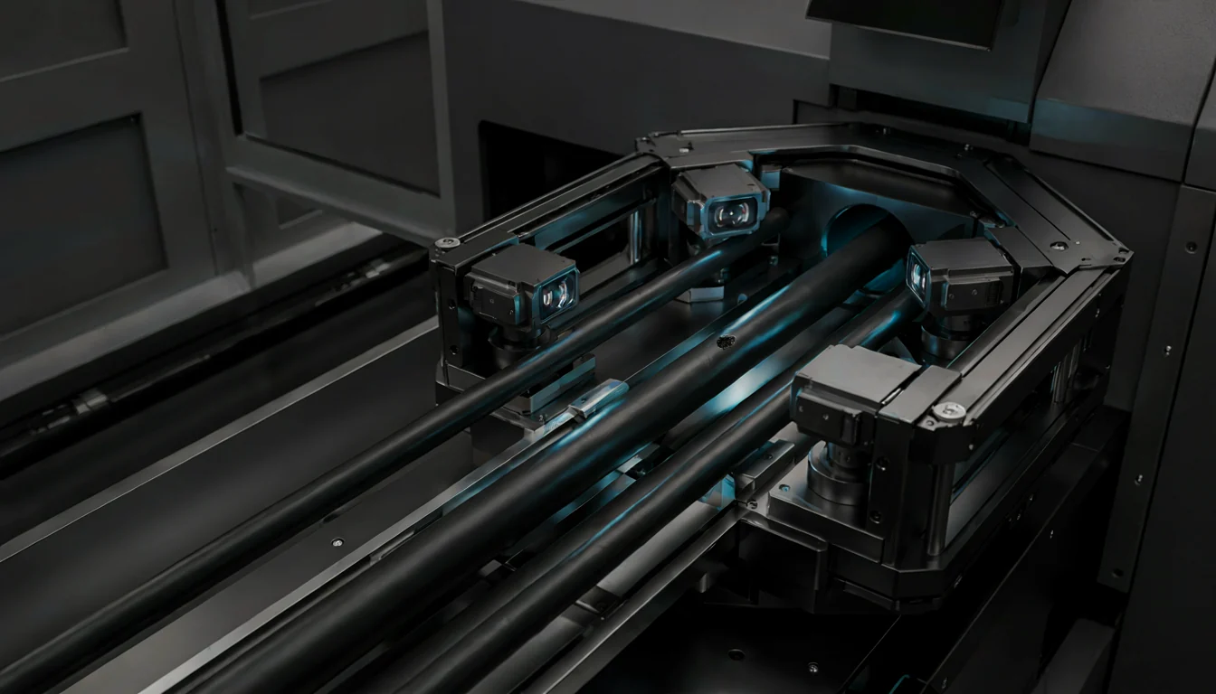
The short answer: define the cable family, observable defect, decision boundary and production response before testing. Then challenge the system with held-out samples at the agreed line speed, vibration, colour and lighting conditions, reporting escapes and nuisance calls by defect class. Vision can create continuous evidence for visible surface anomalies; it cannot establish dielectric integrity, wall thickness, compound properties or compliance of the complete cable from surface images alone.
Why one accuracy number is not an acceptance result
Pinholes, scratches, lumps, dents, contamination, print errors and braid-coverage faults are not one statistical population. They differ in size, contrast, orientation and frequency. A dataset dominated by good cable and obvious faults can produce an attractive aggregate accuracy while concealing escapes in a small but consequential class. Acceptance results should therefore be separated by defect class, with unknown or manual-review outcomes reported rather than forced into a confident label.
A camera data sheet does not close this gap. EMVA 1288 provides a common method for measuring and presenting machine-vision sensor and camera specifications, which helps component comparison. Application performance still depends on optics, illumination, circumferential coverage, motion blur, triggering, surface reflectivity and the available defect evidence. Component characterization is a design input; the production object remains the acceptance target.
| Quality question | What inline vision can contribute | Evidence that remains separate |
|---|---|---|
| Scratches, lumps, dents and contamination | Detection, location and stored imagery within validated size, contrast, view and speed limits | Acceptance limits from the applicable product or customer specification; destructive or material analysis where required |
| Pinholes or sheath damage | Visible anomalies that are not hidden by geometry, glare or insufficient sampling | IEC 62230 defines a spark-test method for detecting defects in cable insulation or sheathing; applicability depends on cable construction and the product specification |
| Diameter, ovality or profile change | Continuous trends and anomaly positions when geometric measurement is explicitly designed and calibrated | Measurement capability, calibration and the applicable cable requirement; a surface camera is not automatically a qualified dimensional gauge |
| Insulation or sheath thickness | Normally cannot be established from the outside surface of a complete cable | IEC 60811-201 and IEC 60811-202 specify methods for insulation and non-metallic sheath thickness respectively |
| Electrical, mechanical, thermal or compound performance | Cannot be replaced by appearance classification | Tests selected for the actual cable and market; for example, IEC 60502-1:2021 specifies construction, dimensions and tests for particular 1 kV and 3 kV extruded-insulation power cables |
Turn the defect catalogue into testable requirements
“Inspect the cable surface” is not a test requirement. For every target class, record the cable variant, defect definition, size and contrast boundary, possible position, permitted occurrence and downstream action. State whether the result raises an alert, marks a location, slows or stops the line, or enters manual review. Classes without representative evidence should remain explicitly unvalidated instead of inheriting capability from a model label.
Coverage needs the same discipline. “Multi-camera” or “360-degree” describes an arrangement, not a proven view. Fixtures, cable motion, curved-surface highlights and gaps between fields of view can all remove usable evidence. Run known defects around the circumference and along the cable axis to verify visibility, position association and handover between views.
A six-stage production acceptance
- Freeze scope. List cable families, colours, surfaces, diameter range, target defects and quality properties explicitly outside the vision scope.
- Build a held-out challenge set. Reserve accepted and defective samples that were not used for tuning. Cover class, location, orientation and boundary size, with provenance and the human disposition recorded.
- Exercise the real operating envelope. Repeat runs at the agreed maximum speed and representative vibration, ambient light, glare and changeover states. A stationary demonstration is not dynamic production evidence.
- Report by class. Separate detections, escapes and false calls for every target class, plus unknowns. Add nuisance alarms per agreed production unit—such as length or shift—so aggregate accuracy does not hide operating cost.
- Prove the action loop. Trace an image and position record through alerting, marking, disposition and review. Exercise lost triggers, interrupted communication, low storage and recipe change with agreed outcomes.
- Control change. Revalidate the affected defects and conditions after a new cable, colour, compound, speed, camera, lighting setup or algorithm version. Do not silently transfer the old result.
Keep vision, process instrumentation and laboratory evidence distinct
A useful quality map has three layers. Inline vision observes surface condition and appearance trends continuously. Spark, diameter or other inline instruments measure their named physical properties. Cross-section, compound, electrical, mechanical and environmental tests then follow the applicable product standard. Link the layers by batch and position, but do not let one impersonate another. This catches process drift early without turning “looks acceptable” into “the cable is compliant.”
Matrix Dimension perspective
The following is an engineering inference from the public standards above: the first deliverable for a cable-vision project should be a defect catalogue jointly owned by quality, process and automation teams—not a camera list or model architecture. When evaluating a cable inspection platform, start with one product family and a small number of costly, observable defects. Prove the minimum loop from seeing and deciding to locating, acting and reviewing before widening scope. Where an algorithm makes the defect decision and a PLC acts on the line, preserve an explicit interface between them; our guide to AI planning and deterministic execution explains the related control principle.
Scope: This article is a requirements and acceptance framework, not a cable conformity assessment or inspection certification. It does not claim any unpublished speed, accuracy or detection performance for Matrix Dimension products. The responsible parties must select standards, defect limits and test methods for the actual cable, application, jurisdiction and complete normative documents.
Frequently asked questions
Can cable vision replace a spark test?
Not as a general rule. Vision judges observable surface features, while IEC 62230 defines spark-testing equipment, operating characteristics and calibration for detecting defects in insulation or sheathing. Assign each method from the cable construction and applicable product specification.
Is detection rate enough for acceptance?
No. Review escapes, false calls, unknowns, view coverage, speed and environmental conditions by defect class, then verify position records, line actions and manual review.
What if there are too few real defect samples?
Narrow the initial claim. Quality-approved representative samples can support a staged study, but unrepresented classes and boundary sizes should stay marked as unvalidated. Training images or unapproved synthetic defects should not become production evidence on their own.
Sources
These primary sources support the material facts and engineering boundaries discussed above.
- EMVA 1288 — Standard for measurement and presentation of machine-vision camera specifications
- IEC 62230:2006+AMD1:2013 — Electric cables — Spark-test method
- IEC 60811-201:2012+AMD1:2017+AMD2:2023 — Measurement of insulation thickness
- IEC 60811-202:2012+AMD1:2017+AMD2:2023 — Measurement of non-metallic sheath thickness
- IEC 60502-1:2021 — Construction, dimensions and test requirements for 1 kV and 3 kV power cables
Evaluating robot control, bimanual manipulation or a mobile platform?
Talk to Matrix Dimension →