Dual-arm handover acceptance: test relative pose, not two repeatability figures
A handover succeeds when the giver workpiece frame and receiver grasp frame meet within task tolerance at the right time and state. Strong repeatability for each robot does not establish that cross-frame result.
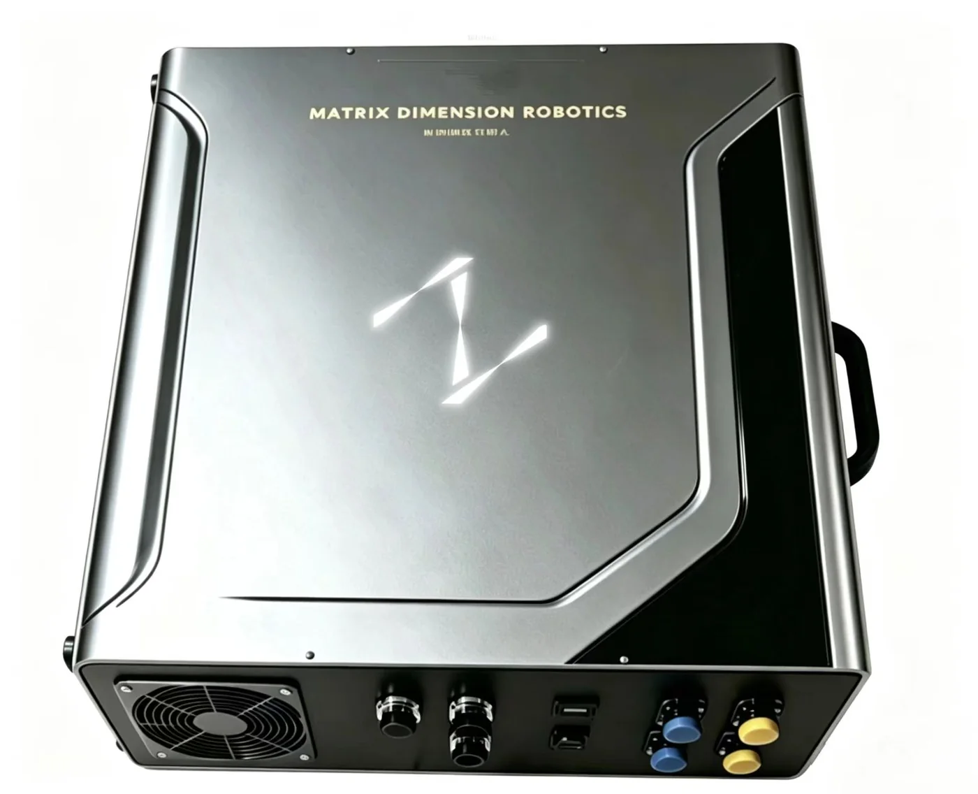
The short answer: do not accept a dual-arm or robot-to-robot handover from two repeatability specifications. The task succeeds only when the giver's workpiece frame and the receiver's grasp frame meet within the required relative pose, at the right time, load and grasp state. A useful acceptance plan separates four evidence layers: individual-arm performance, coordinate registration, coordinated execution and the final process result.
Why two repeatability figures do not close the handover
ISO 9283 provides performance criteria and related test methods for manipulating industrial robots. It is an important starting point for the pose and path behaviour of each arm. A handover adds a cross-system transform chain: workpiece to giver gripper, giver base to a common frame, common frame to receiver base, then receiver flange, TCP and grasp frame.
NIST's multi-robot registration work describes registering a robot's Cartesian frame to another arbitrary frame and quantifying post-registration positioning performance with a reference measurement system. The underlying paper identifies part hand-off between robots as one use of that transformation. Both robots can therefore return consistently within their own base frames while a base registration, TCP, fixture or in-gripper part offset still leaves the two end effectors misaligned.
Four evidence layers for a handover
| Evidence layer | Question | Record | What it does not prove |
|---|---|---|---|
| Individual arm | Can each arm reach consistently at the required pose, speed, load and thermal state? | Pose/path error, load, speed, warm-up and measurement uncertainty | That both arms agree in a common frame |
| Registration | Are bases, TCPs, cameras, fixtures and workpiece frames connected correctly? | Transform chain, fiducial layout, residuals, target-region error and invalidation rules | Dynamic timing or grasp success |
| Coordinated execution | Do both arms arrive, confirm, take over and release on one task timeline? | Timestamps, stage state, pose/velocity deviation, gripper/force signals and timeouts | An undamaged, correctly placed part |
| Process outcome | Does the representative part transfer under real variation? | Success, drop, jam, mis-grasp and recovery by part, pose and cycle condition | That every safety risk is controlled |
Measure relative pose near the exchange—not only calibration residuals
Frame registration commonly estimates a rigid transform from corresponding reference points. A small fit residual does not guarantee a small error at every task point. In a NIST study of robotic insertion and registration error, poor registration misaligned the peg and hole, while the study compared pass/fail outcomes after reducing registration error. For a handover, place validation points throughout the actual exchange volume and measure the relative position and orientation between the grippers—or between the held part and receiver grasp frame—rather than reporting only an average residual at calibration points.
A staged dual-arm handover acceptance
- Freeze the task and tolerance. Define the part, giver and receiver grasps, permitted contact, exchange volume, cycle and final placement. Express position, orientation and contact requirements as task tolerances—not a context-free “total accuracy” number.
- Map the complete transform chain. Name both bases, flanges, TCPs, grippers, workpiece, cameras and common work frame. Record whether each transform comes from teaching, metrology, vision or a mechanical datum, and what invalidates it after a move, tool change, collision or service.
- Confirm each arm independently. Measure both arms at representative exchange poses, speeds, loads and thermal states. This baseline helps separate arm drift from cross-system registration when a task fails.
- Verify relative pose in the exchange volume. Use an independent measurement system or qualified artefact at the centre and boundaries of the volume. Report position and orientation error, distribution, measurement uncertainty and the worst location. NIST's fast-registration demonstration shows two robots repeating an assembly after one base is moved and re-registered to the work volume.
- Test timing and the handover state machine. Record command and feedback time, arrival criteria, grasp confirmation, takeover confirmation and release conditions for both arms. EtherCAT Distributed Clocks documents a network synchronization mechanism, but selecting a fieldbus does not establish application-level handover timing; measure the actual controller, drive and task behaviour.
- Add part and environment variation. Cover real tolerance, mass, compliance, surface friction, presentation, lighting or occlusion, plus startup, thermal steady state and sustained operation. Stratify results so one vulnerable part class is not hidden inside an average success rate.
- Trigger faults and verify recovery. Include missing grasp confirmation, receiver not ready, timing violation, vision loss, part slip, protective stop and restart. At every stage, define who owns the part, who may release it, whether automatic retry is allowed and when an operator must intervene.
A collision-free plan is not a safe handover state
The official MoveIt Planning Scene documentation describes collision and constraint checking against robot state, model and scene, including self-collision, joint bounds and contact reporting. Those checks matter, but a handover often includes deliberate proximity, a period in which both grippers constrain the same object and carefully allowed contact. An incorrect allowed-collision matrix or geometric model can make a plan disagree with the real tool, cable, part or fixture.
The task state machine should therefore distinguish giver-held, receiver-contact-unconfirmed, dual-held, receiver-confirmed, giver-released and clear-of-exchange. Collision rules, gripper state, force signals and timeouts should correspond to those stages instead of being reduced to one offline trajectory check.
Minimum acceptance evidence pack
- Handover task, part family, load, cycle and success/failure criteria;
- Frame tree, TCP/fixture versions and invalidation rules for both arms and sensors;
- Relative position/orientation error and measurement uncertainty across the exchange volume;
- Time-aligned command, feedback, gripper, force/torque, vision and safety-event logs;
- Collision model, allowed contact, speed/force limits and state-machine version;
- Repeated results stratified by part, pose, speed, thermal state and disturbance;
- Failure classification, part ownership, automatic-recovery boundary and manual reset path.
Matrix Dimension perspective
The following is an engineering inference from the NIST work, public standards and open project documentation: for an AI single/dual-arm control hub project, the valuable interface is not merely “send both trajectories.” It is an auditable handover contract covering the common frame, relative target, shared timeline, part ownership, permitted contact, confirmation conditions and failure destination. That contract lets a team isolate geometric error, timing error, grasp failure and recovery logic. For the metrology foundation, see our guide to robot accuracy, repeatability and in-situ calibration; for the software boundary, see AI planning versus real-time execution.
Safety boundary: ISO 10218-2:2025 addresses the integration, commissioning, operation and maintenance of industrial robot applications and cells. This performance acceptance method does not replace application risk assessment, functional-safety design, safeguarding validation or conformity work. A system that includes a mobile platform also requires a separate standards-scope review.
Frequently asked questions
Why can a handover fail when both robots have strong repeatability?
Repeatability describes returning within each robot's own frame. A handover also depends on the common-frame registration, both TCPs, the actual part pose in the giver, timing, grasp confirmation and contact transition. Their errors combine in the relative pose.
Can registration residual be used as handover accuracy?
Not by itself. Validate target registration error between the two end effectors, or the part and receiver grasp frame, throughout the real exchange volume. Include orientation error, measurement uncertainty and the worst location.
Is a simultaneous start enough to prove synchronization?
No. Check the common time base, command and feedback timestamps, actual trajectory deviation, arrival and grasp conditions, and what the other arm does when one arm slows, pauses or faults.
How many handover trials are enough?
There is no task-independent count. Build a stratified sample plan from the part family, poses, loads, cycle and acceptable escape risk, and retain trial-level results rather than only a pooled success rate.
Sources
These primary sources support the material facts and engineering boundaries discussed above.
- NIST — Simplified Framework for Robot Coordinate Registration for Manufacturing Applications
- NIST — Multi-Robot Assembly with Fast Registration
- NIST — Improving Automated Insertion Task in Robotics by Reducing Registration Error
- ISO 9283:1998 — Manipulating industrial robots — Performance criteria and related test methods
- MoveIt Documentation — Planning Scene collision and constraint checking
- EtherCAT Technology Group — Distributed Clocks for high-precision synchronization
- ISO 10218-2:2025 — Industrial robot applications and robot cells
Evaluating robot control, bimanual manipulation or a mobile platform?
Talk to Matrix Dimension →